Hardware
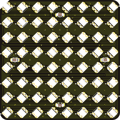
Infinity RGB matrix mini, an 8 by 8 RGB matrix with possibility to extend “infinitely”. The idea of IRM mini is to have connectors on 4 side, for you to connect it with multiple unit of IRM mini, to easlily and neetly expand it as your wish.
Characteristics
Label |
Discription |
Value |
|---|---|---|
5V |
VDD, Power Input |
3.5V~5.5V |
DIN |
Data Input |
0.4V~VDD+0.4V |
Vh |
DIN High Voltage |
0.7xVDD |
Vl |
DIN Low Voltage |
0.3xVDD |
I |
Current |
768mA |
Lv |
RGB Brightness Level |
256 |
DTR |
Data Transfer Rate |
800kbps |
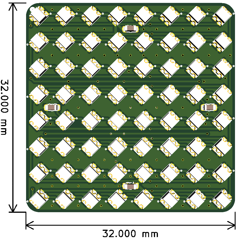
Dimensions
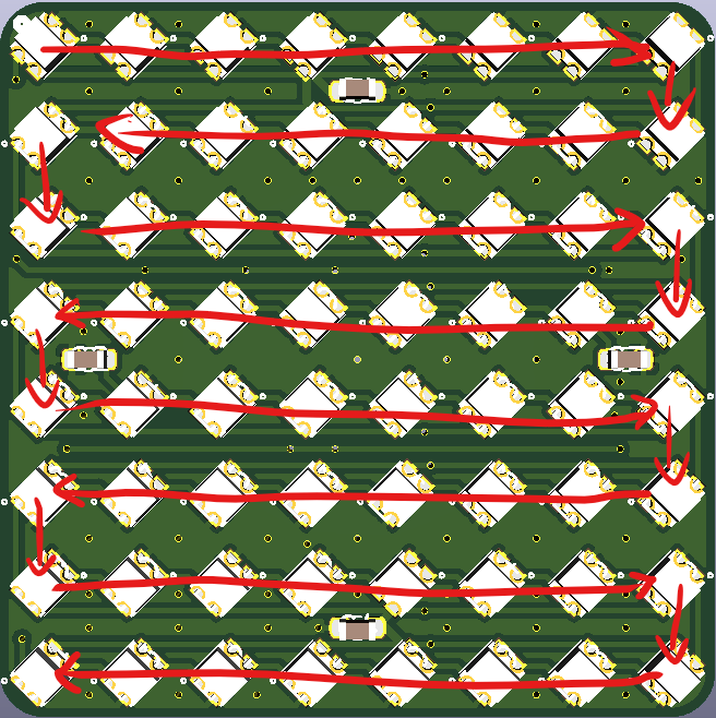
LED arrangment
The first LED is on the top left cornor, and a little dot on top silkprint is showing where is the top left cornor of the board.
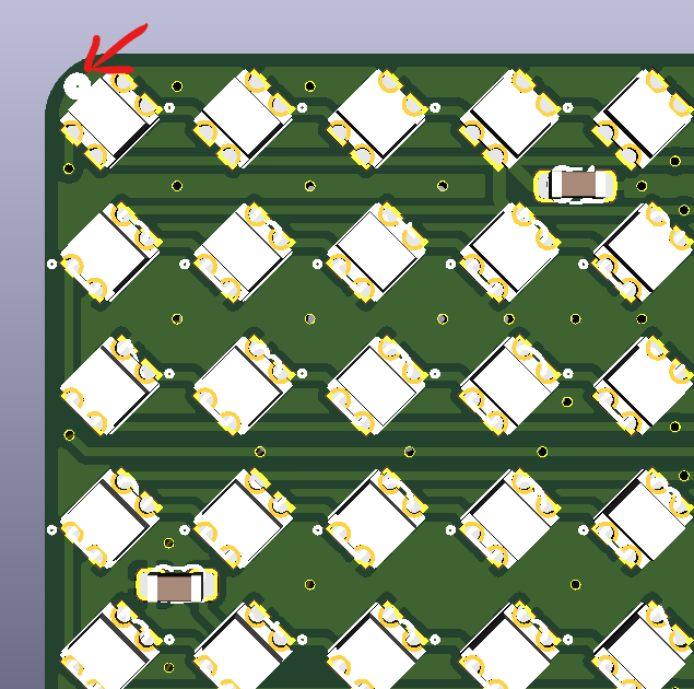
The rest is going zigzag horizontally.
Extension
To extend IRM mini, as it’s the main idea of IRM, you need to first flip all IRM mini units, than arrange it as you wish, for example, a 4x4 unit matrix to exceed a 16x16 led matrix.
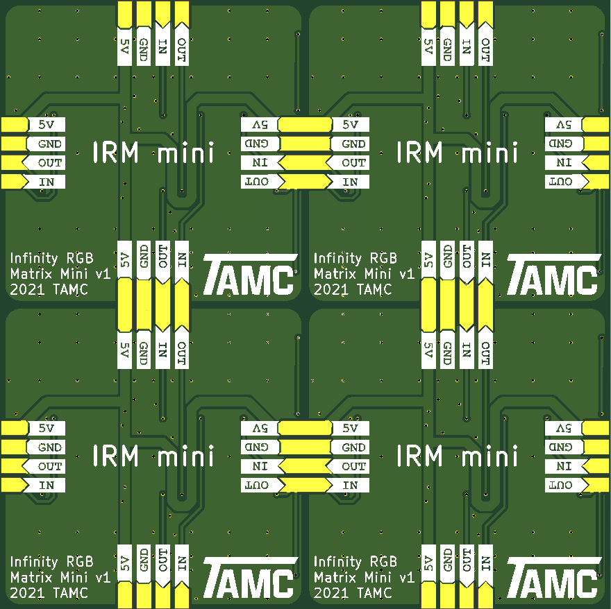
Than solder the solder pad together like this(You can add wires in between, for easier soldering.)
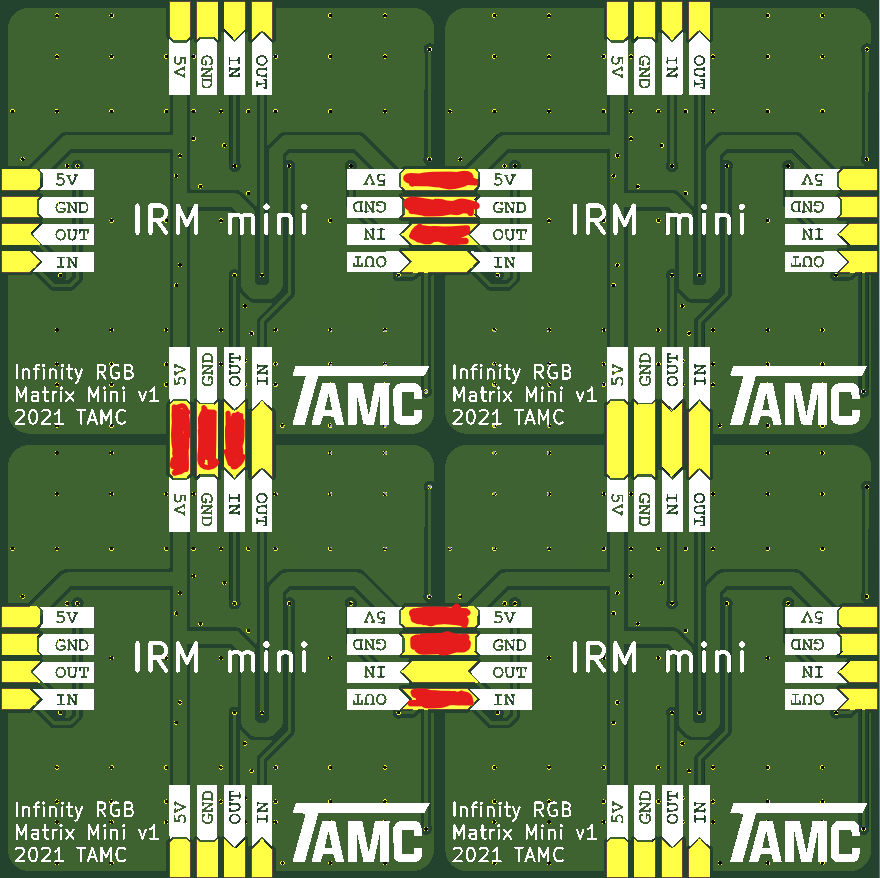
This will make the top left unit the first, and than going zigzag again.
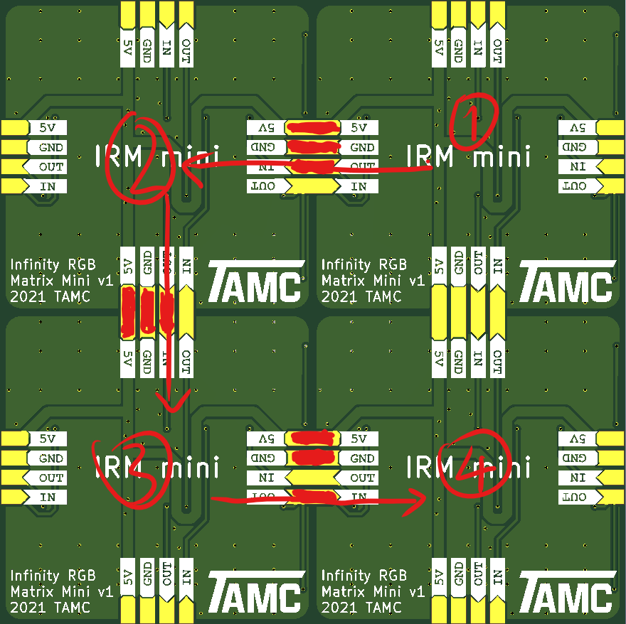
You can see how the connection goes with in and out, and the special desige of the solder pad.
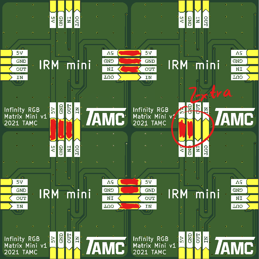
You can also solder an extra power pad for a stronger structure. But do not solder neither In or Out
It’s not the only way to connect it, as all 4 side have both 5V, GND, In, Out. But there are rules should be follow.
In and Out in a set of connection MUST NOT be both connected.
The all boards MUST be connected in a single line, not with any branches, and not a loop.
Power line are parallel, and can be all solder together to provide stronger stuctures.
Avoid short circuit on any pins! A multi-meter checking after soldered is and good habit.